
FAQs
Circular Dichroism Technology Explained
CD Instrumentation FAQs
What type of monochromator do Chirascan systems use?
- A double Czerny-Turner prism monochromator is at the heart of every Chirascan system and produces an intense measuring beam. Light generated by a xenon arc lamp enters the monochromator via an optical coupling, and the monochromator selects horizontal linearly polarised light of defined wavelength and bandwidth, which is then converted to circularly polarised light by a photoelastic modulator (PEM).
Why does the monochromator of Chirascan systems use two prisms?
- Chirascan monochromators use two quartz prisms, each grown as a single crystal. Prisms offer the advantage of improved light dispersion in the far-UV and do not produce higher-order diffraction artefacts associated with grating-based monochromators. Crystalline quartz prisms, in contrast to the more common fused silica type, are birefringent (i.e., have a refractive index that depends on the polarisation and propagation direction of light) so not only disperse light into the component wavelengths, but also disperse high purity vertical and horizontal linearly polarised components.
How does the monochromator of Chirascan systems work?
- As white light is passed through the first prism, it is split into the component wavelengths and the desired wavelength is selected by the intermediate slit. The prisms also separate vertical and horizontal linearly polarised components of light. A mixture of horizontal linearly polarised light at one wavelength and vertical linearly polarised light of another wavelength passes through the intermediate slit. The second prism separates the contaminating vertical linearly polarised light from the horizontal linearly polarised light.

What determines the sensitivity of a CD spectrometer?
- The limit of detection of any spectrometer is determined by the signal-to-noise (S/N) characteristics: the better the S/N, the higher the sensitivity. The S/N ratio is proportional to multiple contributing factors:
S/N ∝ ΔA · (Q · I · t · 10-A) ½
ΔA: CD, expressed as differential absorbance
A: absorbance
Q: quantum efficiency
I: light intensity
t: time
How can the signal-to-noise ratio be maximised?
There are four options to maximize S/N:
- Optimize the sample absorbance
The equation above maximises for A = log(e2) ≈ 0.87 AU, which is therefore the optimal absorbance for making CD measurements. To get a spectrum with an optimal S/N ratio, one should aim at an average absorbance close to this value.
- Increase intensity of the incident light from the monochromator (I)
The intensity, I, can be maximised by using spectrometers with prism-based monochromators rather than grating-based monochromators, because prisms allow for a higher light-throughput. Moreover, the use of two prisms that are both polarising causes a large wavelength/polarisation state dispersion which means that wider slit settings can be used to maximise throughput of required light while rejecting stray light.
- Increase quantum efficiency of the detector (Q)
The quantum efficiency, Q, of a detector is its efficiency in turning an incident photon into an electronic signal and can be maximised by using advanced photodiode detector technology. While photomultiplier tubes (PMT) have been used in spectroscopy for many years and still feature in the Chirascan VX, new, high-gain, solid state detectors afford larger sensitivity. Chirascan V100 and Chirascan Q100 systems use a large area avalanche photodiode detector (LAAPD) to provide significant improvements in quantum efficiency in the ultra-violet, visible, and near-infrared regions.
- Spend more time collecting and averaging data points (t)
This approach should be the last resort for improving the S/N ratio as it decreases productivity and prolonged exposure to intense UV light can cause photolysis of proteins that are particularly photolabile.
Maximizing light intensity and detector quantum efficiency significantly reduces the time required to carry out a measurement: quality data is collected in less time even when working under time-limited conditions such as analysis of photolabile samples.
What is a photoelastic modulator (PEM)?- The photoeleastic modulator (PEM) converts horizontal linearly polarised light to circularly polarized light. The PEM consists of an optical element which is a silica block (depicted by the green box in the animation below), and a piezoelectric element that is attached to and tuned to the resonance frequency of the optical element.
How does the photoelastic modulator (PEM) work?
- Horizontal linearly polarised light (grey in the animation below) generated by the monochromator passes through the optical element of the PEM and remains horizontally polarised if the PEM is at rest. However, upon operation of the spectrometer in CD mode, an alternating drive voltage induces vibrations of the piezoelectric element, which exerts mechanical stress on the optical element so that the latter is being stretched and compressed.
- The mechanical vibrations imposed on the optical element modulate its birefringence and, in turn, the polarisation state of the transmitted light.
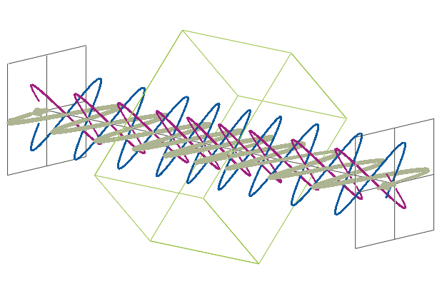
How does light from the monochromator interact with the PEM?
- The horizontal linearly polarised light coming from the monochromator can be described by two orthogonal components, of which one is aligned along the short axis (purple wave in the animation below) and one along the long axis of the optical element (blue wave in the animation below).
- Due to the modulation of the birefringence of the optical element, the refractive index for the component along the long axis changes periodically. As a result, the component along the long axis is alternatingly slowed down and sped up relative to the component along the short axis.
- The resulting phase shift between the two components of the polarised light creates light which is
- left-/right-handed circularly polarised at phase shifts of exactly 90° and -90°, respectively
- horizontal linearly polarised at a phase shift of 0°
- elliptically polarised at any phase shifts between 0° and ±90°
- The instrument electronics ensure that samplings are only carried out when the PEM generates circulary polarised light. The oscillations of the piezoelectric element and, in turn, the samplings occur at a frequency of 50 kHz.
Related:
Circular Dichroism FAQs